
First off all I want to thank Ricardo Lima Caratti for the wonderfool library that he have written for that chip.
Tis project is a proof of concept. Don’t expect to have characteristic of a professional receiver. But its small size, big frequency range and multimode capabilities, make it interesting and useful, at least for me.
The designee is standard heterodyne receiver. I have used the Si5351 for VFO and ADE-1 as a mixer. If frequency for the AMI input of the Si4735 is 10.7MHz. For the FMI input (because there is no filter) you must make some experiments what will be the best frequency for you. In my case that’s something around 65 MHz .
I have used BGA427 as amplifiers on the input and as IF amplifier after the filter for the AMI input.
For the Si4735 there is a option for 32kHz crystal or you can use clk1 of the Si5351 as a oscillator.
On the PCB i have put a charging circuit for a 3.7V Li-Ion Battery. There is a option for external EEPROM and as a Audio Amplifier I have used TDA2822.
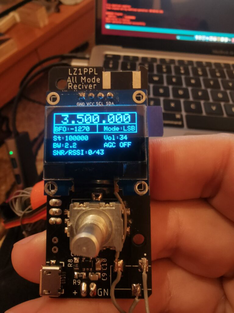
The frequency range of the receiver is from 100khz to 220 MHz for the AM and SSB. and from 100kHz to 240MHz for the FM mode. I have tried the receiver on several bands and modes, it doesn’t have the sensitivity of the professional ones but for its size it works pretty well. For now it doesn’t support NBFM mode, but I have try the reception of some HAM Repeaters, Its not great but its ok 🙂 .
It will be a good idea to calibrate the Si5351 before using the receiver. This will help especially on SSB reception.
Probably there are many improvements that can be made (on Hardware and on Software), and i will be glad to here some recommendations and what you think of the receiver.
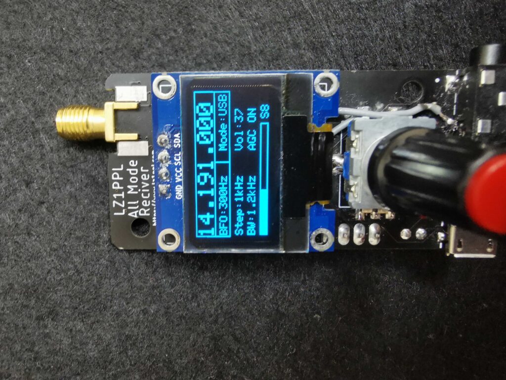
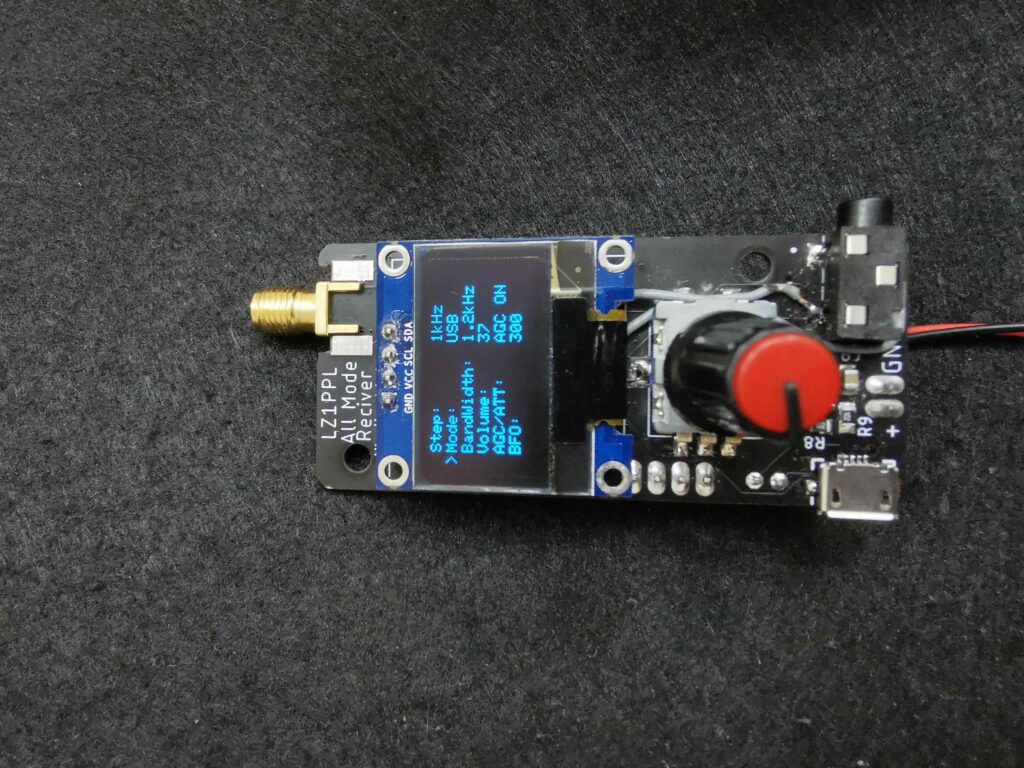
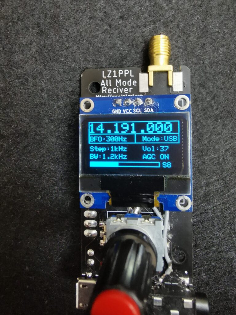
As a microcontroller I have decided to use STM32f103. The settings of the receiver are stored on the internal EEPROM. The menu is accessed whit two short presses on the encoder and whit one long press you can store the current frequency in the EEPROM also. In the menu you can change the frequency step, the mode of the receiver, the bandwidth , the Volume, AGC on or off and in the SSB mode you can change the BFO +- 1.2khz.
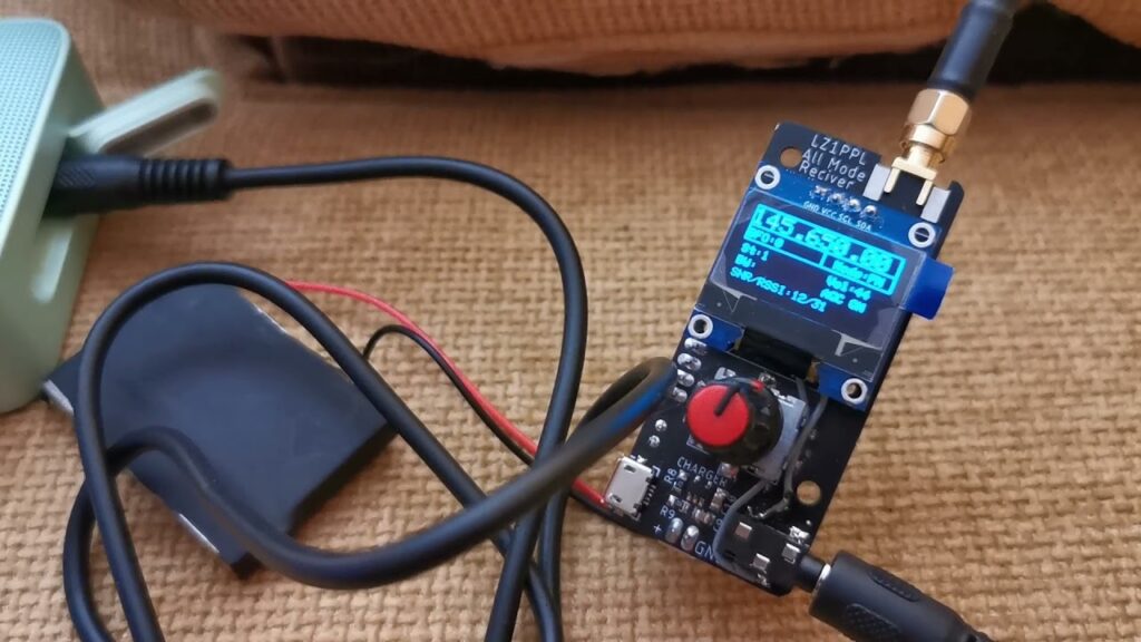
Here are some photos and videos of the receiver. And the links for the Schematic and for the code will be bellow.
Schematic: https://github.com/LZ1PPL/Si4735/blob/main/Hardware/si4735v2.3.1.pdf
Code: https://github.com/LZ1PPL/Si4735/blob/main/Si4735-Si5351_STM32_FM.ino
Repo of the project: https://github.com/LZ1PPL/Si4735
Hi Plamen,
Are the files that you have in Github updated from what I see in the photos (added parts or modifications have all been implemented)? Also, I see that there’s a mini-USB connector on the left side of the receiver, how does one program this receiver with the Arduino sketch? Is this directly from the PC or is there some other interface required? GREAT design and project – I love the size of the receiver even though it may not be optimal in performance – it’s still ‘good enough’.
Thanks in advance for your advice on the above – 73
Marty, KN0CK
Zdraveĭ Plamen,
Aktualizirani li sa faĭlovete, koito imate v Github, ot tova, koeto vizhdam na snimkite (vsichki dobaveni chasti ili modifikatsii sa vnedreni)? Sŭshto taka vizhdam, che ima mini-USB konektor ot lyavata strana na priemnika, kak se programira tozi priemnik sŭs skitsata na Arduino? Tova direktno li e ot kompyutŭra ili se iziskva nyakakŭv drug interfeĭs? STRAKHOTEN dizaĭn i proekt – obozhavam razmera na priemnika, vŭpreki che mozhe da ne e optimalen po otnoshenie na proizvoditelnostta – vse pak e „dostatŭchno dobŭr“.
Blagodarya predvaritelno za vashiya sŭvet otnosno gornoto – 73
Marti, KN0CK
Hi Marti,
First thanks for the interest in the project.
The errors that you are seen in the photos are corrected and the files are updated. I have ordered new PCB’s, but they are still not here, so I can’t guarantee 100% that everything is correct.
The USB is mainly used for charging the battery. The USB port is connected to the processor, but noting is implemented yet. The programming of the board is true SWD connector on the side of the board (you can see the 4 pins on the photos). To program the board you will need some kind of SWD programmer like STlink v2 for example. You can use this programmer with Arduino IDE.
73
What is minimum frequency step for HF SSB? (without switching to BFO)?
Minimal step is 1Hz
YOu mean normal continous tuning witgout that stupid switching to “bfo”. Like normal TRX with real “adult” encoder? 😉
Amazing. 😉 Thank You.
MAc sp9mrn
Exactly, normal tuning step not BFO.
I have added as tuning steps 1Hz, 10Hz, 100Hz, 1kHz, 5kHz, 10kHz, 100kHz and 1MHz.
I can add even more, but I think that’s enough.
I’s enough. Magnetic encoders from AS have reliable prices and resolution is up to 4k ticks (as i remember).
Only a little play with mechanics…
MAc
I think he means RS not AS which seems meaningless . as in RS components. , a UK based company. cheers TEF
First of all, congratulations onsuch a nice development around the Si4735! I was not aware of such advanced RF frontend designs elsewhere. On the FM mode, do you think a SAW filter such as SF2040B could be applied between the mixer output and the Si FMI?
Hi,
I’m thinking about adding a filter, but I haven’t decided yet should I add a simple LC filter or SAW filter. The problem is that there isn’t enough space on the Pcb. Probably I will have to redo it again.
Nice project.
Thanks for sharing.
73.
PU2CLR.
I’m glad that you liked it. And thanks once again for the great work on the library.
Nice project.
Thanks for sharing.
73.
PU2CLR.
I’m glad that you liked it. And thanks once again for the great work on the library.
Hello and greetings from Portugal!
Congratulations on your project. How can we have access to purchase one unit?
Cheers!
Luís, CT2FZI
Hi,
I don’t have any kits for sale yet. Ther are still some changes that I want to make. May be after that I will make some kits and assembled boards for sell. Many people are asking for them. I will try to find some time to make the changes I want to test and will decide after that.
Hello and thanks for the headsup.
If you like, I would like to be a beta tester. Let me know when you have available the revised board, material cost and shipping cost to Portugal.
Cheers!
LL, CT2FZI
When you do make changes I suggest you include firmware mods to make it easy to integrate with
CW Tx
AM Tx
DSB Tx
Either as a Tx /Rx pair or as a true transceiver .
I have already left posts on the site re cutting the guts out of the 4 StateGroup QRP Hilltopper design (RF PA ) and reusing it as a 3 to four W CW Tx . NB not Mountain topper but Hilltopper as re engineered for free by the famous Dave Benson of Vermont., USA
TEF in Nz.
Hello and greetings from Portugal!
Congratulations on your project. How can we have access to purchase one unit?
Cheers!
Luís, CT2FZI
Hi,
I don’t have any kits for sale yet. Ther are still some changes that I want to make. May be after that I will make some kits and assembled boards for sell. Many people are asking for them. I will try to find some time to make the changes I want to test and will decide after that.
When you do make changes I suggest you include firmware mods to make it easy to integrate with
CW Tx
AM Tx
DSB Tx
Either as a Tx /Rx pair or as a true transceiver .
I have already left posts on the site re cutting the guts out of the 4 StateGroup QRP Hilltopper design (RF PA ) and reusing it as a 3 to four W CW Tx . NB not Mountain topper but Hilltopper as re engineered for free by the famous Dave Benson of Vermont., USA
TEF in Nz.
Hi , thanks for sharing such a cool project
what other changes do you have planned ?
73’s de 9H5BM
Jason
Noting special. I just need to fix some errors on the original PCB and I want to add a bandpass filter for the FMI input.
Hi
You should consider then LPF88A, devices, they are small and tuned to the broadcast frequencies.
http://www.szhjd.com/product/a002d.html
73’s de 9h5bm
The integration of Si5351 sketch with Si4732(35) was very good, nice project, congratulations!
J. CesarSound.
Thank you.
The integration of Si5351 sketch with Si4732(35) was very good, nice project, congratulations!
J. CesarSound.
Thank you.
Hello LZ1PPL, thank you for sharing this nice project of a portable wideband receiver.
I have completed a few minor “cosmetic” modifications to the PCB (audio amplifier TPA0253, LDO TPS73633) – I did not make any modifications to the RF frontend because I am not an RF electronic engineer and now I am thinking about sending PCBs for production or waiting for modifications with added FMI filter. Do you have any time estimate for rev2 release with added bandpass filter?
https://drive.google.com/file/d/1vXoxTNSKNDHk1A6K1OGKkvPjJ9o2KkUt/view?usp=sharing
thank you for reply
Best Regards
Radek
I will send it to the Pcb factory probably in the beginning of next week.
OK. Thank you. I’ll wait.
I have added the new schematic whit the PBF to the GitHub page. But I haven’t tested yet the PCB. Its still in production.
So the bpf will work on the I.F. of 65mhz – did you calculate the capacitance and inductors ?
I use the page rf tools for the filter values https://rf-tools.com/lc-filter/
between 60 to 70 Mhz
I get 6pf with 912 nh and 3pf with 1.5uh caps to the ground are 430pf, a 13nh coil can be shunted with the cap too.
73’s
I didn’t put any values on purpose. Because I’m not sure what frequency will be the best. I’m planing to test on different frequencys.
Hi LZ1PPL Please add This project gerber files.
Best regards.
Hi Radek,Please add This project gerber files.
Best regards.
I will add them later, when I have a time.
Can support WFM stereo ?
Yes.
Can support WFM stereo ?
Yes.
Hi, LZ1PPL, thank you for sharing this nice project of a portable wideband receiver.Please add this project firmware bin and hex code file.
Best Regards
I have the hex file ready, but didn’t upload it because I had a complaint that it didn’t work when you upload it thru CubeMX. I must investigate that further.
I see the latest design with battery and charging circuit, but the power seems to be unable to be turned off?
Yes, that’s a mistake that I need to fix.
I see the latest design with battery and charging circuit, but the power seems to be unable to be turned off?
Yes, that’s a mistake that I need to fix.
Excelente trabajo,por favor informeme si pone kits a la venta.
Saludos
Excelente trabajo,por favor informeme si pone kits a la venta.
Saludos
Thank you so much for this project.
I am interested in purchasing the kit for this receiver when it is available.
73, John WB4YAL
Thank you so much for this project.
I am interested in purchasing the kit for this receiver when it is available.
73, John WB4YAL
Hello,
Is this available yet as a kit or ready built?
John
G8TDU
Hello,
Is this available yet as a kit or ready built?
John
G8TDU
I would like to buy the kit . Let me know how I can get 1
73, NITIN VU2CAN
I would like to buy the kit . Let me know how I can get 1
73, NITIN VU2CAN
I’m waiting for you to upload the GERBER file to repeat the project. Thank you, I wish you good luck! 73
I’m waiting for you to upload the GERBER file to repeat the project. Thank you, I wish you good luck! 73
Hi
With layers have this board?? I’m very interest this radio and try to order PCB on JLC but in file see 5 layers??
Hi
With layers have this board?? I’m very interest this radio and try to order PCB on JLC but in file see 5 layers??
Hi! Great project! I am now making my board about this scheme. I have one question. Is it possible to replace F103C8T6 on F103C6T6? Is there enough memory for the program?
Hi! Great project! I am now making my board about this scheme. I have one question. Is it possible to replace F103C8T6 on F103C6T6? Is there enough memory for the program?
hi , thanks for sharing , does gerber file and bom file available now in 2022 ? thanks.
hi , thanks for sharing , does gerber file and bom file available now in 2022 ? thanks.
Please give me the latest version of the Sketch?
The available version did not find any radio stations
Thanks
EP3HNM
Please give me the latest version of the Sketch?
The available version did not find any radio stations
Thanks
EP3HNM
Hello
Very interesting project but I have a small question. Is the SFECV10M7JA00-R0 filter replaceable by the SFECV10M7KA00-R0?
Thank you.
Hello
Very interesting project but I have a small question. Is the SFECV10M7JA00-R0 filter replaceable by the SFECV10M7KA00-R0?
Thank you.