I know i haven’t posted anything from a very long time, but i have decided to post one of my latest projects, on which i work more than a year. I hope it will be interesting for some of you.
In the last couple of years i have been to many ARDF (Fox Hunt) competitions, and this sport is of interest to me, but i have noticed that the receivers that competitors are using are very old, or very expensive. That’s way i decide to develop a cheep and good receiver for me and the kids that i help to teach on this sport.
After very long period and some errors, i successfully have developed two variants for receivers.


The first variant uses Varicap for VFO, and the second one (which i prefer) is using digital synthesizer for the VFO.
I will publish the both variants, but the description that i will give below will be for the one whit the synthesizer.
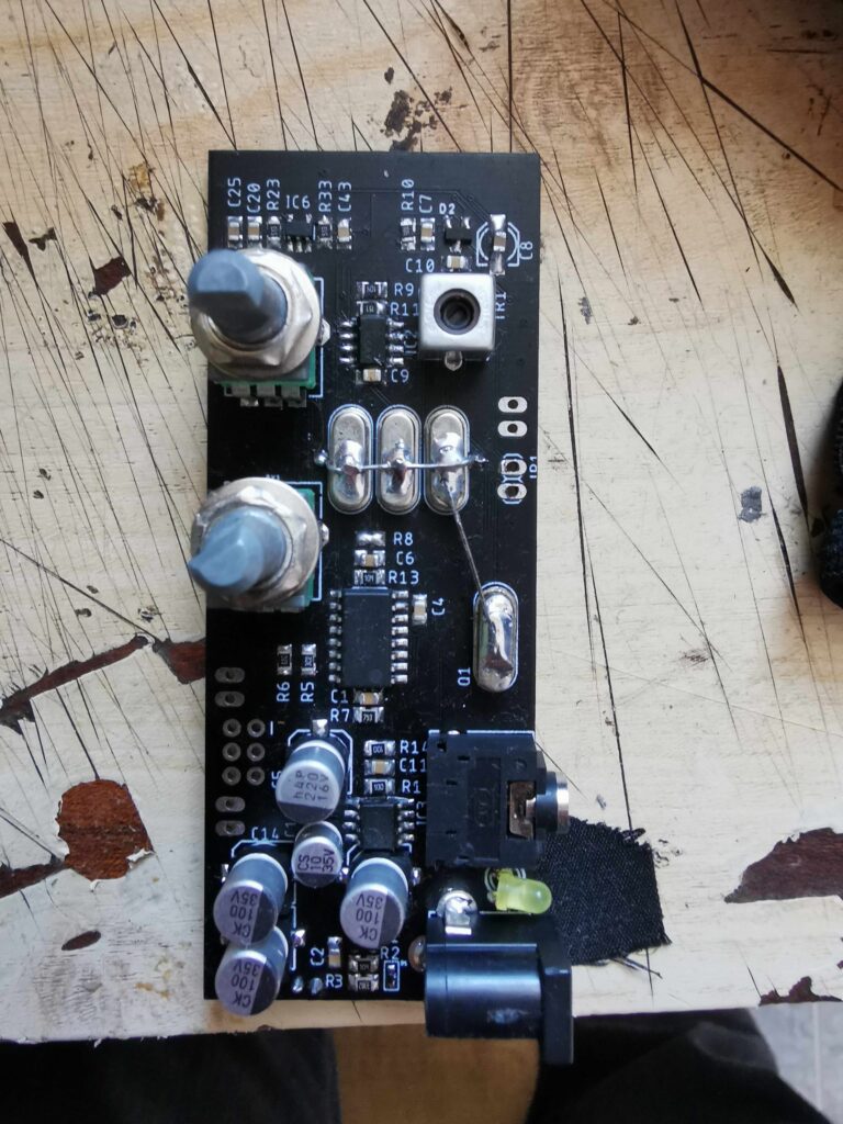
The receiver uses the superheterodyne scheme of the receiver whit the IF frequency of 8.192 MHz. As a mixers I’m using the well known SA612. The IF frequency is chosen to be 8.192 MHz because there are many quartz crystal resonators on the market whit that frequency. And they are pretty cheep. I’m using this kind of resonators to make the IF filter. For the filter the resonators whit similar parameters must be chosen. I have bought 200 of them and after i have checked the parameters i have been able to make 40 crystal filters whit them. Part of the rest crystal resonators I;m using for the BFO of the receiver.
For the IF and input amplifier I’m using BF904. My first idea was to use the BF1112, but they are a little harder to find, so i decided to use BF904 instead. But if you have any BF1112 you can use them as well, just be careful because the pin-out is not exactly the same.
I’m using two gaits transistors and that give me the ability to use the second gate to regulate the sensitivity of the receiver. This is very useful. when you are close to the transmitter you can regulate the sensitivity so that you have good minimum and maximum of the receiver. Some of the receivers that i have seen used to regulate the audio signal, but i think its better to regulate the sensitivity then the audio signal.
For the resonance of the first transistor I’m using variable inductance of 2.7uH. And for the second I’m using inductance of 8.2uH the second one doesn’t need to be tuned. I have tried to make the schematic whit minimal components that should be tuned.
As i have said before, for the BFO I’m using one of the crystal resonators plus variable capacitor C15.
In the schematic there is also ton-generator circuit that is used for close search of the transmitters. For the ton generator I’m using CD4046 and the switch TC7W53F. Instead of TC7W53 you can use TC4W53, they both have the same pin-out.
As for the Audio amplifier I’m using LM386.
Whit the help of FDN336 and the diode 1n4148 i have made an auto turn on/off circuit. When you plug the headphones the receiver will turn on, and when you remove the headphones the receiver will turn off.
As the receiver will work whit two Li-Ion batteries I’m using as a charging circuit MCP73213.
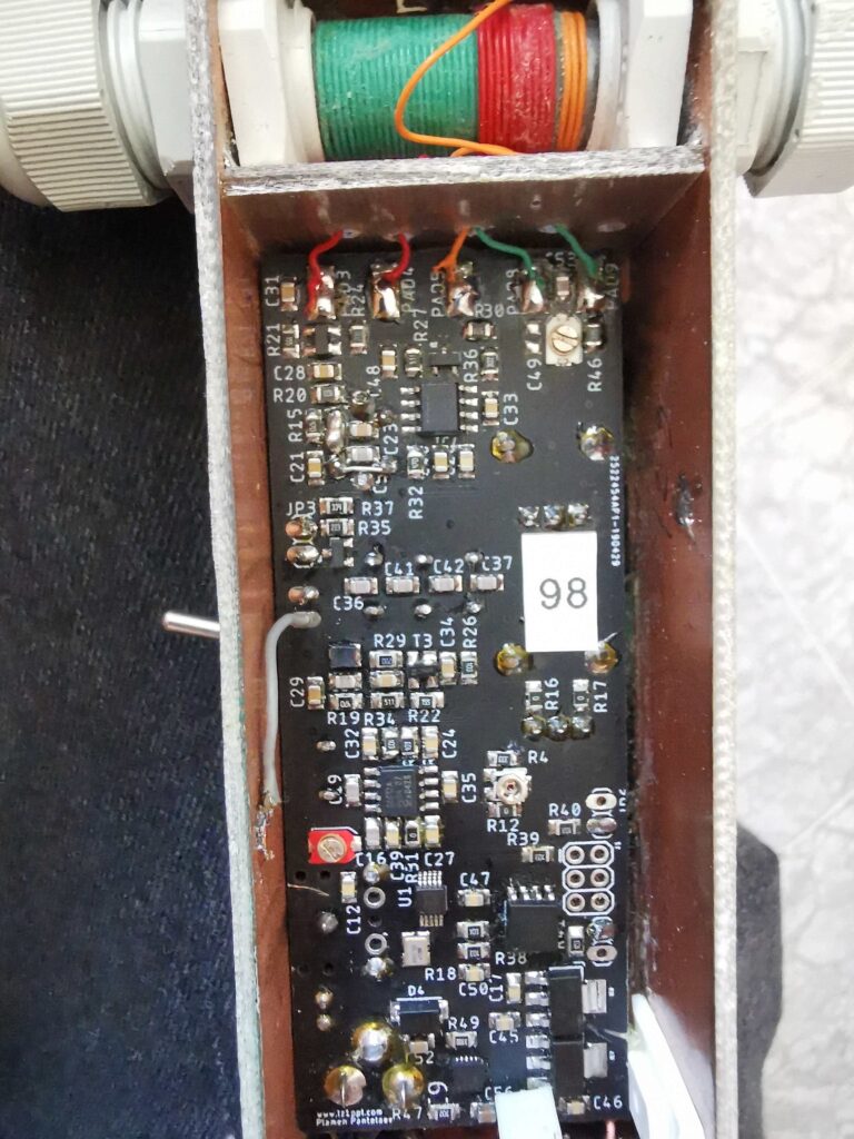
The capacitors C49, C53, C54 and the resistor R46 are used to tune the ferrite antenna.
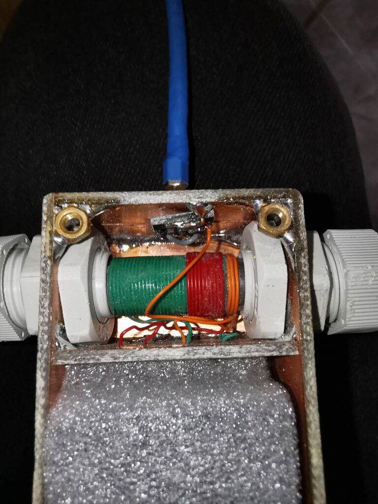
For the ferrite road antenna you will need a ferrite road approximately 10 cm long and 10 mm in diameter. Wind 32 turns of wire on the road and live approximately 3-4 cm leads, on top of them wind another 10 turns and live leads as well. For the coupling of the vertical antenna wind 3 more turns close to the other ones, and that’s all, your ferrite road antenna is done.
The capacitors C49, C53, C54 and the resistor R46 are used to tune the ferrite antenna.
For the switching of the vertical antenna I’m using low capacity transistor, in my case BF999, In this way, it will be possible to use a 5 cm long vertical antenna.
This part of the schematic is given as a separate scheme because its important to be maximal close to the vertical antenna. I have made a separate board for this and have soldered it directly to the vertical antenna.
I have left for the last the VFO part of the schematic, because this is the main difference between the both variants of the receiver.
As a VFO im using Si5351, it is just perfect little synthesizer for this purpose.
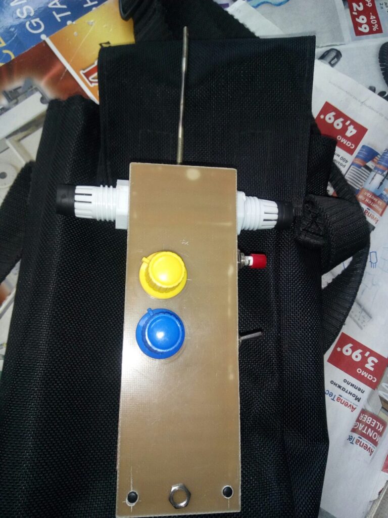
To control the Si5351 I’m using Attiny85 microprocessor. For control of the frequency I’m using a 10k potentiometer and the ADC of the microprocessor . this give me exactly 1024 steps. The band that i need to tune the receiver is 3.5 MHz to 3.6 Mhz, so whit the 1024 steps that i can use i can make every step to be exactly 100 Hz which is perfect for my case.
As i have two free pins on the microprocessor , i have decided to put two more buttons and to use them as memory banks. In that way the competitor can store two frequency on this buttons and switch to them during the competition whit just one button press.
Usually the SI5351 has I2C Address 0x60, but the ones that i have have I2C Address 0x62. Therefore i have made two variants of the HEX file for both variants.
I will give BOM file for the parts that are used in this projects whit links from where i have buy my parts. I’m sorry that most of the links are to one Bulgarian online parts suppler, but i don’t think it will be hard for you to find the parts. Especially as this suppler that I’m using is representative of Farnel. So i guess you will be able to find the parts in Farnel or Mouser catalog as well.
All my project can be used under the restriction of CC BY-NC (Common Creative NonCommercial) license.
If you like what i do you can always sponsor my next project, or buy me a beer.
Links:
Scheme for receiver whit SI5351
Scheme for the receiver whit Varicap
Scheme for the vertical antenna
Hex file for the Attiny85 I2C Address 0x62
Hex file for the Attiny85 I2C Address 0x60
Одлично! 73, Z33T
Одлично! 73, Z33T
Браво од Z35O
Браво од Z35O
Where can i purchase the PCB from?
73 de ZS5LT
Where can i purchase the PCB from?
73 de ZS5LT
[…] LZ1PPL Similar approach to VK3YNG but using an SI5351a for VFO. […]
[…] LZ1PPL Similar approach to VK3YNG but using an SI5351a for VFO. […]
Hi,
There is a VERY similar (practically the same) design published by HG0HK. So who I have to ask for permission from, if I would like to use some details?
Who is the original author?
Best regards,
George, SWL
Hi,
This project was made by me and one friend of mine Valeri Georgiev who died 3 years ago. I don’t know if he have used some ideas from others, or this is just the same idea. I personally didn’t use others designs. Actually I have made 5 different designs before publish this one. But any way. You can use any part of the designee under CC BY-NC-ND (Creative Commons NonCommercial-ShareAlike) license.
Hi,
There is a VERY similar (practically the same) design published by HG0HK. So who I have to ask for permission from, if I would like to use some details?
Who is the original author?
Best regards,
George, SWL
Hi,
This project was made by me and one friend of mine Valeri Georgiev who died 3 years ago. I don’t know if he have used some ideas from others, or this is just the same idea. I personally didn’t use others designs. Actually I have made 5 different designs before publish this one. But any way. You can use any part of the designee under CC BY-NC-ND (Creative Commons NonCommercial-ShareAlike) license.